


Structural Design
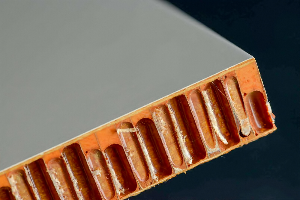
FRP composites can be analysed by many engineering methods. Depending on shape, panel stiffening system, and intended use, a variety of choices exist to evaluate loads and structural performance.
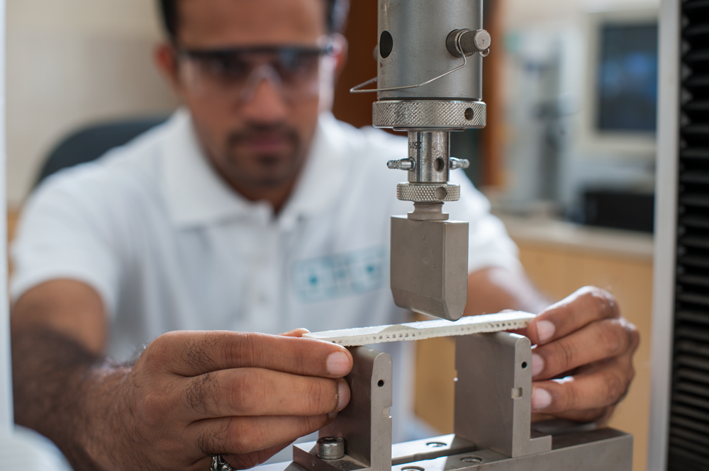
Often, due to the complexity of composite structures, the most representative method of analysis is physical laboratory testing. Numerical methods such as Finite Element Analysis (FEA) are valuable during the early design stage for predicting structural behaviour and optimising laminate schedules.
BFG's experienced FRP experts can assist in laminate design and provide composite structure design recommendations tailored to your project requirements.
Service Loads
Dead load for FRP panels is relatively small compared to live loads due to the material's low self-weight. Designers should pay particular attention to uplift loads from wind, aerodynamic effects, and panel geometry.
Important thermal considerations include:
- Temperature gradient through the panel thickness
- Effects of soffits and returns on thermal behaviour
- Differential properties of facing materials and their response to temperature change
- Surface colours and their effect on heat absorption
FRP panels should be designed for horizontal and vertical contraction and expansion without excessive buckling. Minimum design loads should be determined per the governing building codes applicable to the project.
Handling Loads
Loads from transportation and site handling can exceed design service loads. It is essential to follow the manufacturer's handling instructions at all stages.
Proper lift-points, centre of gravity, and dead-load magnitude should be clearly indicated on shop drawings. Any special handling requirements must be clearly stated to avoid damage during transit and installation.
Anchorages and Connections
FRP structures require both inter-panel connections and panel-to-structure connections. Common connection types include:
- Traditional fasteners with gaskets for weatherproofing
- Bonded and bolted connections for structural integrity
- Inter-panel bonded connections for seamless assemblies
Connections to supporting structures typically use anchor bolts or high-tension bolts with gaskets. Bearing strength checks are critical, as laminate design and fibre orientation directly affect bolt dimensions and connection capacity.
Provision for Movement
Design must allow for expansion and contraction of FRP members due to thermal effects or differential deflection of the supporting structure. Information on joints and tolerances should be clearly documented on shop drawings to ensure proper accommodation of movement.
Design and Tolerance
Tolerances are set giving consideration to material properties, manufacturing processes, and installation conditions. These are discussed on a project-by-project basis with the primary structure designer. Key elements for consideration include:
- Inserts and embedments — must be corrosion-resistant and properly embedded with bonding pads to ensure long-term durability
- Joints — an integral part of total system design, assessed for both performance and cost, and designed to accommodate structural movements
- Support structure — must have adequate capacity to resist all reactions from FRP members under design loading conditions
Tolerance
Tolerance is defined as the permissible variation from specified requirements. Tolerances must be established for dimensions, locations, and critical features of every FRP component to ensure proper fit and function during assembly and installation.
Appearance
At the sample and mock-up approval stage, acceptable variations of colour, texture, and uniformity are determined and agreed upon. The finished surface should present a pleasing appearance with minimal variation from the approved sample.
No chips, cracks, or foreign matter should be visible on the finished product surface.
Product Dimensional Tolerances — Fabrication
Fabrication tolerances are established by economical and practical production considerations. The individual skill of craftsmen, pattern makers, mould makers, and FRP laminators determines the achievable accuracy.
Actual thickness may deviate from design thickness depending on the manufacturing process and laminate schedule. The project contract should specify acceptable tolerance values for all critical dimensions.
Installation Tolerances
Cumulative errors from the primary structure, supporting structures, and FRP parts can cause problems if not properly assessed during the design phase. Compatible tolerances across all elements are essential.
Close collaboration between the manufacturer and the building design team is critical to achieving a successful installation. Gaps between adjacent members must be maintained to allow free thermal expansion and contraction without inducing stress in the panels.